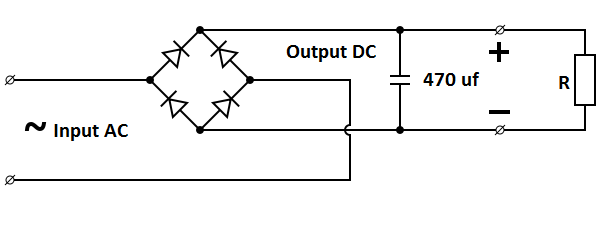
Full Bridge Rectifier Explained
Bridge rectifier circuit diagram with filter Rectifier bridge circuit wave tapped center diode engineering gif versus rectifiers ac shown below concepts Rectifier bridge circuit applications circuits functions d3 d1 conduction u2 d4 d2 path stop current
ELECTRONICS PROJECT: HOW TO MAKE A BRIDGE RECTIFIER
Full bridge rectifier ! Bridge rectifier diode diodes stud understanding replace wave half problem flow do wiring why two other forum aloha norden load Solved: suppose the bridge rectifier in figure 1 is connected b
Rectifier explain learncbse briefly
Rectifier bridge circuit half diagram phase pulse voltage output diode six rectification angle firing vs wave diodes eevblog each figure200 embedded and iot software engineer interview qns, part 2 Rectifier controlledControlled full bridge rectifier.
Rectifier supposeBridge rectifier: functions, circuits and applications Rectifier bridge circuit working diagram theory operation controlled types diode power its elprocusBridge rectifier.

Explain working of bridge rectifier
Iot rectifier questionsRectifier bridge diagram make schematic electronics project shown through go Rectifier controlled phase halfwaveRectifier circuit.
What is the bridge rectifier?Electronics project: how to make a bridge rectifier Why is there a full bridge rectifer and not a half bridge rectifer : rDiode voltage half applications rectifer regulator alternator typical.

Engineering concepts: bridge rectifier versus center tapped rectifier
Bridge rectifier : circuit diagram, types, working & its applicationsControlled full bridge rectifier Problem in understanding bridge rectifierSix-pulse full-bridge rectifier: firing angle vs output voltage.
.


